Study of welded and bolted joints
BACKGROUND
For more than 15 years now we have been gaining extensive experience in the study of all types of mechanical joints between wind turbine components, covering those that are on the blade to those on the foundation. These analyses require an advanced and accurate approach that combines different techniques, from mathematical modelling using finite elements techniques to analytical calculations using different codes, with the aim of ensuring the strength and durability of the wind turbine assembly.
The analysis of welded and bolted joints is a skill that can be used in any sector and device that is included in the wind energy sector because of the large number of joints that are used. A wind turbine is simply a machine with a number of joined components where the fatigue and useful strength of these must be certified by certain private entities to guarantee their durability.
It is very common for the joints between components of a structure or machine to be the weakest points in the path mechanical loads generated by the turbine travel on their way to the tower anchoring assembly. With this capability for analysing the joints between components, the technician can properly size them to guarantee the joints carry out their function of joining components with the proper strength and thus maximise and guarantee the service life of the machine.
RESULTS
The analysis enables to obtain an assessment of the joints in their original definition and also to propose, in the event that the minimum requirements are not met, countermeasures or changes to the parameters in order to iteratively re-check until the objectives are met. In conclusion, this analysis allows designing and optimising the joint by accurately determining the factors that affect its design.
A common practice is to include the methodology and results of these calculations in the reports that are sent to the customer as well as submitted to the pertinent agency in charge of certifying the machine.
EXPERIENCE
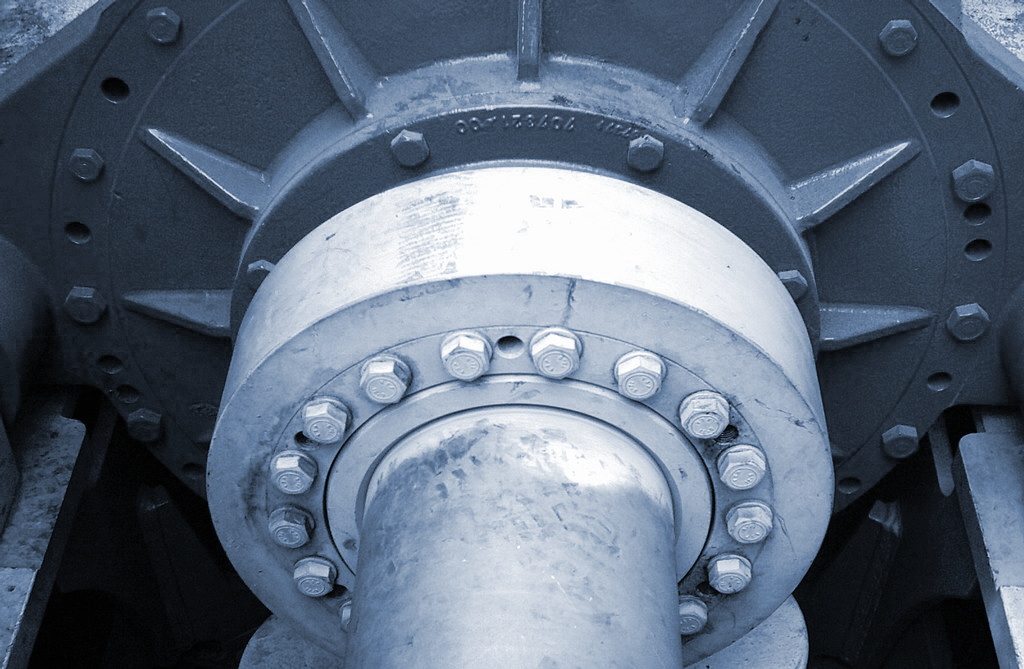
This type of calculation for large customers is a common task that we have been carrying out from our beginnings, in wind energy as well as other areas of activity and for different interest groups. Specifically on wind turbines, the most common bolted joints are: 1) between the blade root and bushing 2) between the bushing and rotor shaft 3) between the nacelle and the tip of the tower 4) all the flange joints along the tower 5) at the union between the bottom part of the tower and the corresponding section of the foundation. The welded joints are also analysed, which, although fewer in number proportionally on a wind turbine, are also found on the rear frame as well as on other specific areas where there are welds.
The stakeholders or interest groups are varied and include from developers and/or manufacturers of machines and towers, to operation and maintenance (O&M) departments or wind park owners, and in all cases the process is just as rigorous.
METHODOLOGY
Because of the accuracy required when calculating bolted and welded joints, the use of finite elements modelling (FEM) is a common practice. These are high precision models with a high degree of refinement and detail. SOLUTE has extensive experience in FEM modelling, which allows devising the best possible approach. For example, a common practice is the use of modelling techniques where the information originating from large models with greater scope are applied to refine in a specific area where the welded or bolted joint is located.
Different commercial codes may be used for creating the FEM models, although in all cases the modelling includes a first case of pretension loading of the bolts, a definition of frictional contacts between surfaces and a defined refinement in a way that allows obtaining information from the area of interest to carry out the subsequent analytical calculation.
In the case of circular bolted joints, specific approaches are made that allow conducting a highly accurate discretization of several points on the circular perimeter of each bolt, because this way we can reflect the variability of the loads as a result of their direction. This is of special interest for the fatigue analysis where we have a historical series available with a lot of information about the module and direction, which can and must be used in the analysis.
Codes, standards and design guides (DNV, Eurocode, VDI2230, etc.), are normally used, in addition to other approaches internally designed by us. For extreme calculations, normally the obtained value is the usage margin, and in the case of fatigue, the damage accumulated during the estimated period, which is normally 20 or 25 years. The methodology that is applied allows a traceability such that when the value does not meet requirements, we can analyse the cause and propose changes in the joint design or parameters and check them to see if they are compliant.
Automotive
Interior modules
This discipline ensures the stiffness, stability and durability of the elements to provide customer's a sense of high quality.
Wind
Design and development of electric grid plans
Design and implementation of electrical drawings for low, medium and high voltage grids as well as collector substations and high voltage aerial lines for onshore wind parks