Aerodynamic in wind turbines
BACKGROUND
Analysis and functional design of components subjected to aerodynamic forces, primarily two-dimensional profiles and three-dimensional blades.
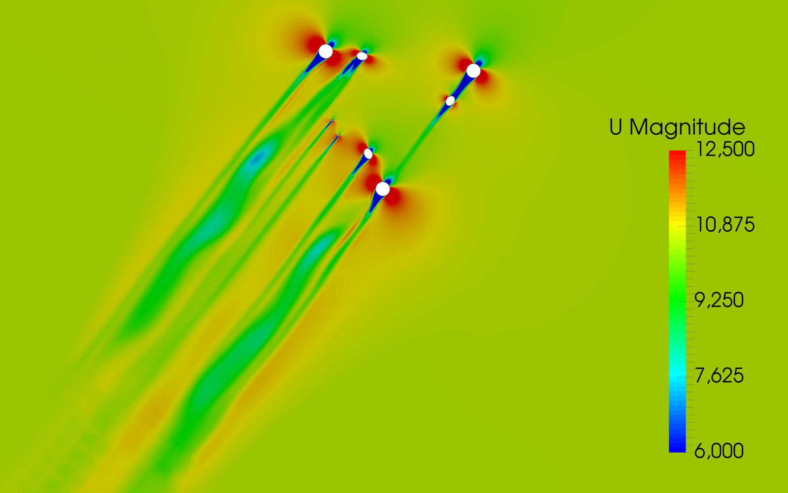
Based on the regulation applied to wind turbine design, models of interest are built and solved using CFD (Computational Fluid Dynamics) techniques. Then they are post-processed, and modifications are proposed of the design to meet the objectives.
The design and optimisation of aerodynamic components, primarily a wind turbine blade. Even though blades are the most important components and the most sensitive to aerodynamic behaviour, there are others such as the tower or the nacelle that can also be analysed from this perspective.
With a focus on the blades, we try to find shapes that allow taking as much advantage as possible of the wind's kinetic energy. At the same time, other requirements are met, like reducing the noise generated by the turbine or the excessive aerodynamic loads they are subjected to.
RESULTS
What is supplied is a definition of the geometry of the components studied (normally blades or profiles) that respond to their demands. This is normally accompanied by a report that includes the aerodynamic behaviour of the analysed components.
EXPERIENCE
SOLUTE has conducted several tests and studies at an internal level, which could be applied to any customer in the wind energy sector.
The first step is to model the geometry, provided in drawings or 3D files, through CAD software - such as CATIA or SolidWorks. Then the simulation parameters are defined.
METHODOLOGY
The established objectives are used as a basis, taking into account the limitations, both constructive as well as assembling or weight. Then, the current legislation is reviewed such as IEC 61400 as well as the state of the art of similar machines and then we begin working on the model and the load cases.
The first step is to modernise the geometry, supplied in drawings or 3D files, using CAD software such as CATIA or SolidWorks. Then, the simulation parameters are defined: type of mesh, fluid flow domain, turbulence model, if it is transitory or stationary, simulation time, fluid properties, etc.
Once the model has been pre-processed, we move forward with the simulation, which requires a great calculation capacity and possibly renting external servers to reach the required computational power. There are a large number of CFD solvers available and we will choose the one that best adapts to the type of simulation: OpenFOAM, Ansys Fluent, Star CCM+ or AcuSolve.
Once the simulation is complete, we must process the results, analysing the parameters of interest such as the profile lift, its strength or other derived values such as the power or moment coefficients. Using software such as META or EnSight we can visually analyse the results in order to more easily understand the model's behaviour.
If the initially obtained results do not satisfy the set objectives, modifications of the model are proposed, and the prior steps are iteratively repeated until the requested objectives are met.
Software
Databases
An efficient way to store information that allows recording and subsequently classifying products, users, profiles, accesses and any other type of valuable feature.
Nuclear
Design and optimisation of structural components in nuclear power plants
Capability that guarantees the integrity of the reactor as well as safety in terms of radiation leaks in spaces that are restricted and protected against natural disasters such as earthquakes or hurricanes.